In this article we will talk about the transmit mediums used to transmit data. The mediums used to transmit data are mainly divided into two parts.
1.Guided mediums
2.Unguided mediums
What are guided mediums?
Guided media are media that we can physically touch, which are used to transmit data from one network device to another network device. After using these, the frequency does not change when the data is transmitted. Therefore, the damage to the data is very less. Now let’s see what are the examples of guided mediums
Twisted pair
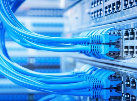
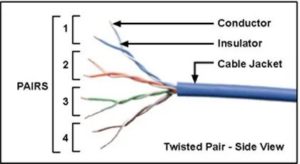
Twisted pair cables are cables that have a plastic cover around a copper wire and are designed by wrapping two wires together. Even though there are two wires like this, only one wire carries data. Also, due to the cable, the electric effect that can occur during data transmission is minimized. Similarly, the twisted pair of the RJ 45 cable used for your home telephone line is used.
Coaxial cables
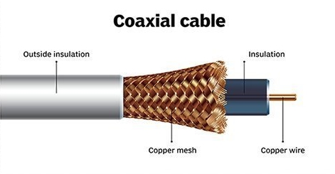
A plastic cover is placed around a copper wire and the cables covered with a copper mesh woven over it are called Coaxial cables. It is correct to say that a cable like this is used for the antenna of the TV used in your home.
Fiber optics
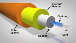
After plastic covers with many layers, cables designed with a very thin glass tube are called fiber optics. You have often heard and seen on social media that if you want to get a speed network connection, switch to fiber optics. Due to the thin glass tubes in the fiber cables, no damage is done to the data. Also, that method helps a lot to get a speed connection.
What are unguided mediums?
Data can be transmitted from one network device to another network device, media that we cannot physically touch are called unguided media. These are transmitted through the atmosphere. Now let’s see what are the examples of guided mediums.
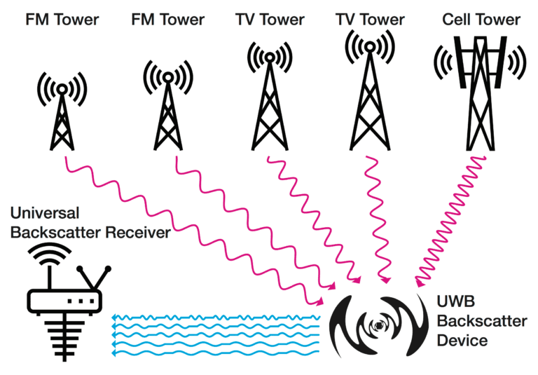
Radio waves
It is because of these signals that we can listen to the radio channels we know in normal life. And it is because of its frequency that it is possible to separate radio wawas from one another.
Infrared
By using infrared, we can transmit data even at a very low frequency. Infrared signals are used in wireless mouse, wireless keyboard and TV remotes.

Micro waves
Micro waves signals are used to transmit data over long distances. Short signals with higher frequency are used in this.
Now let’s see what kind of interference can happen when data is transmitted in this way?
When data is transmitted through any of the Guided / Unguided media we talked about, the original form of the data changes as the distance to be transmitted increases. Because when the distance increases, normally the strength of the signals decreases. So there are two types of damages that can be caused by this case.
Attenuation
Attenuation is the decrease in frequency due to the gradual decrease in the energy of the wave as it passes through an electrical medium. As a solution to this, before the end user receives the relevant signal, a repeater should be used to regenerate the signal.
Distortion
The change in amplitude of the signal due to the inductance capacitance of the medium used for data transmission can be called distortion.
Noise
When data is transmitted, we can simply call it noise from the environment outside the signals.
Ex – heat, lightning, cross talk, noise caused by electric waves (impulse)
Modulation
Modulation is the basic characteristics of a wave, the frequency, amplitude and phase are changed, made to match the transmission medium, an electromagnetic wave is mixed with a high frequency signal and used to transmit data. The technology is exactly right. We can do this technology for analog signals as well as digital signals.
Now let’s see what is Analog Modulation?
We call it analog modulation to change the amplitude, frequency or phase of the carrier wave according to the wave containing the data. This method is often used to transmit low energy waves over long distances. As an example, this method is used a lot in radio waves and television media.
Now let’s see how the analog modulation method is applied according to amplitude, frequency and art.
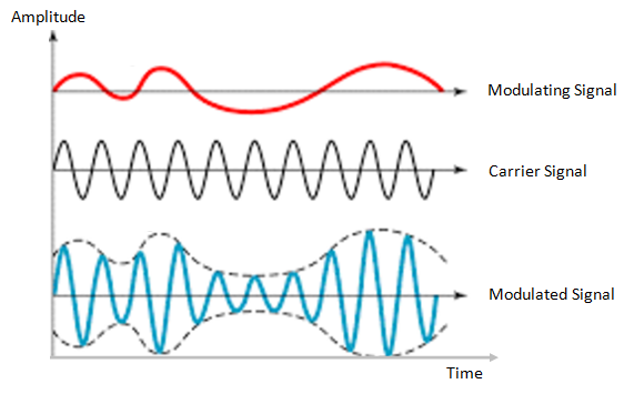
(1) Amplitude modulation
The method of changing the amplitude of the carrier wave according to the signal being sent is called amplitude modulation. In this case, the frequency and art do not change.
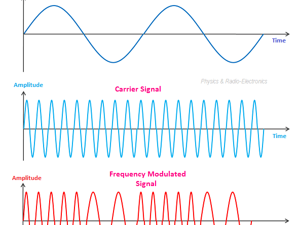
(2) Frequency modulation
The frequency wave that is produced by reducing the wave size in places where the voltage of the analog wave used for transmission is high and increasing the wave size in places where the voltage is low is called frequency modulation or frequency modulation.
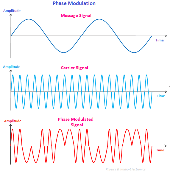
(3) Phase modulation
Converting the wave to an angle of 180 degrees in places where the voltage of the transmitted signal is high, and finishing the transmitted wave by ending it as 0 degrees in places with low voltage can be called art simulation.
what Digital Modulation is?
A digitized wave (it is made to match the mode of the transmission medium and is simulated with the carrier wave and transmitted is called digital modulation.
Now let’s see how the digital modulation method is applied according to amplitude, frequency and art.
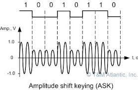
(1) Amplitude-shift keying (ASK)
The method of designing signals by reducing the height of the wave in the places corresponding to 0 and creating the height of the wave in the places related to 1 of the numbered wave that is directed to the transmission medium is called Amplitude-shift keying.
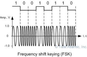
(2) Frequency Shift Key (FSK)
The method of designing signals by increasing the wave size in the places corresponding to 1 and decreasing the wave size in the places related to 0 of the numbered wave that is directed to the transmission medium is called Frequency Shift Key.
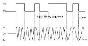
(3) Phase Shift Key (PSK)
By sending the data to the transmission media, converting the wave to an angle of 180 in the places related to 1 and setting the angle to 0 in the places related to 0 is exactly correct if it is said that it happens in the Phases Shift Key concept.
Pulse Code Modulation
A very famous modulation method used when converting an analog signal into a digital signal is called Pulse Code Modulation. What happens in this case is that an analog signal is translated step by step into a binary code or binary code.
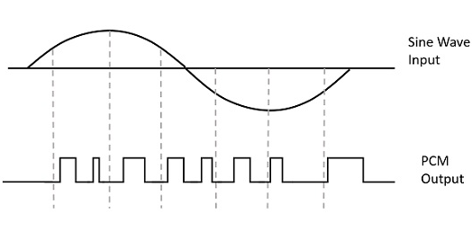
what are the basic characteristics of pulse code modulation?
(1) Sampling
Sampling the input analog wave at constant intervals is called sampling.
(2) Quantization
In this step, the unwanted parts of the sampled wave are removed.
(3) Encoding
Converting the quantized wave into a binary code is called encoding.
what are the encoding techniques.
Analog data to analog signals
Analog wave amplitude modulation, frequency modulation and art modulation belong to this.
Analogy data to digital signals
Pulse code modulation is an example of this.
Digital data to digital signals
This includes Amplitude Adjust, Frequency Adjust and Art Adjust.
Digital data to digital signals
Non return zero (NRZ), Bi phase encoding and block coding belong to this.
ok Now we talked about data transmission mediums for so long. Talked about Signals. He talked about how to convert analog to digital and digital to analog signals. So, have you ever wondered what we use these for in practical life? Are there other ways to use it? Now let’s see about it.
Public Switch Telephone Network – PSTN (Public Switch Telephone Network)
Public Switch Telephone Network or PSTN is the network that provides telephone facilities to the whole world. It is made up of many things like telephone lines, optical fibers, cables, microwave tracks, communication satellites, marine cables.
Also, all the devices that are connected like this are connected to each other from the switch centers. In the past, this has worked as an analog system. But nowadays, with the advancement of technology, everything except the telephone line has become a completely digital system.


